

In this article, we will explore the different methods of evaluating Gmax including:
- Outline why you should evaluate this key parameter
- Explain the standard evaluation test method
- Explore details of Bender Element test method
- Go through the typical configuration of the Bender Element with a triaxial system
- Introduce the benefits of the new Bender Element system from Wykeham Farrance
One of the important roles of a Geotechnical engineer is to predict soil behavior and soil structure interaction resulting from earthquakes, explosions or machine & traffic vibrations in order to improve the safety of built infrastructure.
And to do this, engineers need to perform a low-strain dynamic analysis required for a variety of geotechnical applications. One of its key parameters is the assessment of a soil Initial or Maximum Shear Modulus Gmax, normally associated with shear strain levels of about 0.001% and below.
Standard Method
Usually, the standard way of evaluating this parameter is to perform a Resonant Column test. It consists of dynamically exciting the top of a cylindrical soil specimen restrained at the base with an electrical motor generating torsional forces. The fundamental mode of vibration is determined from the maximum motion; resonance frequency, Shear Wave velocity S-Wave and Shear Wave Modulus calculated using the Elasticity theory. The corresponding shear strain is then calculated from the motion amplitude.
There is another way…
Thanks to research carried out by universities, the Soil Mechanics testing industry had developed an easier, faster and more economical solution that works with a triaxial system and measures the Maximum Shear Modulus Gmax: the Bender Element System.
What’s a Bender Element System?
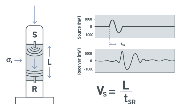
The Bender Element system consists of a piezoceramic transmitter and receiver, which are energized to produce the shear waves through the soil sample. The travel time of the shear wave from the transmitter to the receiver is determined via a specific software that allows the user to calculate the shear wave velocity quickly and easily. Application of the theory on shear wave propagation in an elastic body indicates the value of the shear modulus Gmax of the soil from measurement of Shear wave velocity Vs is given by:
Gmax = ρ · Vs²
where ρ is the mass density of the soil specimen.
How does the piezoceramic Bender Elements work?
The piezoceramic Bender Element is an electro-mechanical transducer that converts mechanical energy (movement) either to or from electrical energy.
The single Bender Element consists of two thin piezoceramic plates, which are rigidly bonded together with conducting surfaces between them and on the outer edges.
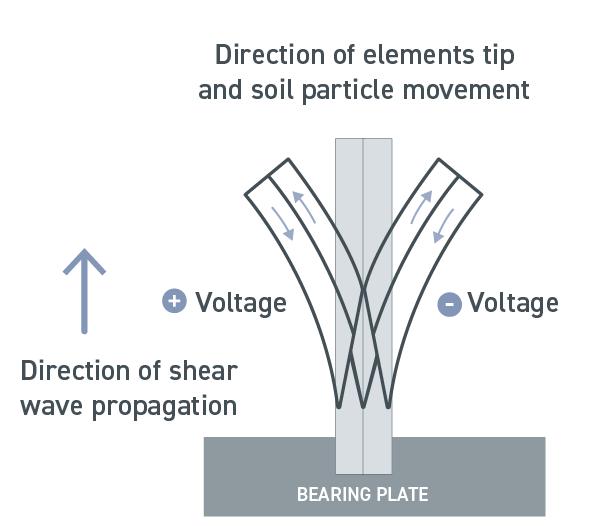
The polarization of the ceramic material in each plate and the electrical connections are such that when a driving voltage is applied to the element, one plates elongates and the other shortens.
The net result is a bending displacement, which is greater in magnitude than the length change in either of the two layers.
In other terms, when the Bender Element is forced to bend, one layer will go into tension and the other into compression: this will result in an electrical signal, which can be measured.
How can a Bender Element system be fitted with a Triaxial System?
In Soil Mechanics applications, the Bender Elements are mounted into inserts, fixed into the pedestal and top cap of a triaxial cell. They protrude edge-first into the soil specimen and act as a cantilever.
When excited, the Bender Element bends from side to side, pushing the soil in a direction perpendicular to the length of the element, thus generating a large coupling factor with the soil.
This produces a shear wave, which propagates parallel to the length of the element into the soil sample.
At the other end of the soil sample, another Bender Element is forced to bend producing a measurable electrical signal.
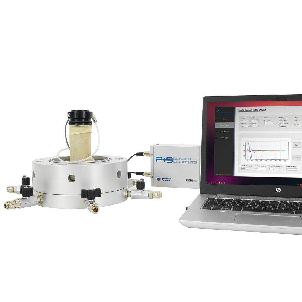
What about the New all-in-one Bender Element System from Wykeham Farrance?
Our innovative automatic system is composed of a single Master signal conditioning Control Unit, the brain of the system, including:
- a waveform generator
- an analog-to-PC interface
- a virtual oscilloscope software
- all connecting cables
Bender Elements are excited by a waveform signal generator (power and measuring system). The electrical output signal is converted into digital and transmitted to PC via an interface and processed with the virtual oscilloscope software.
The system can automatically estimate the Shear Modulus Gmax by applying specific algorithms. Plus, the user can also manually evaluate this parameter leaving maximum flexibility when interpreting data.
The new system, in addition, allows to measure the longitudinal P-wave and consequently the longitudinal modulus or constrained modulus Mmax
So in conclusion, what are the main advantages of our new Bender Element System?
- Easy to install in a Triaxial system
- Quick and economical: a Bender Element System allows to estimate the Maximum Shear Modulus Gmax avoiding the use of more complex equipment like the Resonant Column System
- The new compacted design of the Master signal conditioning unit which includes waveform generator, analog-to-PC interface, virtual oscilloscope software
- User-friendly software allowing the automatic estimate of Gmax
- Possibility to measure P-Wave velocity and the Longitudinal/constrained modulus Mmax
If you have any concerns or more questions about use and application of Bender Elements System, then feel free to get in contact with us and visit Bender Elements web page.

